Microstrip impedance refers to the characteristic impedance of a microstrip transmission line. A microstrip is a type of transmission line used to carry high-frequency electrical signals on printed circuit boards (PCBs) and integrated circuits (ICs). It consists of a thin conducting strip, typically made of copper, placed on top of a dielectric substrate, which is usually a non-conductive material like fiberglass or ceramic.
The characteristic impedance of a transmission line is an important parameter that determines how signals propagate along the line and how well they match with the connected devices or components. In the case of microstrip, the characteristic impedance is primarily influenced by the dimensions of the strip, the dielectric constant of the substrate, and the height of the substrate.
The microstrip impedance is typically expressed in ohms (Ω) and represents the resistance that a transmission line would present if it were terminated in a pure resistance, without any reflections. It is a crucial parameter for impedance matching, which is the process of ensuring that the source impedance, transmission line impedance, and load impedance are appropriately matched to minimize signal reflections and maximize power transfer.
A circuit trace routed on an outside layer of the PCB with a reference
plane (GND or VCC) below it, constitutes a microstrip layout. Use the
following microstrip impedance equation to calculate the impedance of a
microstrip trace layout:

Using typical values of W = 8 mil, H = 5 mil, T = 1.4 mil, the dielectric
constant, and (FR-4) = 4.1, with the microstrip impedance equation,
solving for microstrip impedance (Zo) yields:
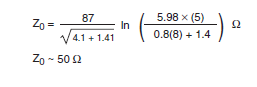
The measurement unit in the microstrip impedance equation is
mils (i.e., 1 mil = 0.001 inches). Also, copper (Cu) trace thickness
is usually measured in ounces for example, 1 oz = 1.4 mil).
Stripline Transmission Line Layout

W = width of trace, T = thickness of trace, and H = height between trace and two reference planes.
Microstrip Trace Impedance with Changing Trace Width
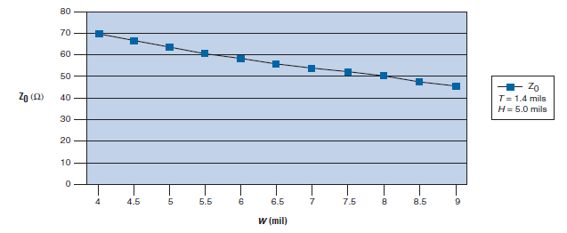
Microstrip trace impedance with changing trace width(W), using the values in the microstrip impedance equation, keeping dielectric height and trace thickness constant.
Microstrip Trace Impedance with Changing Height

Microstrip trace impedance with changing height,using the values in the microstrip impedance equation, keeping trace width and trace thickness constant.
Microstrip Trace Impedance with Changing Trace Thickness

Microstrip trace impedance with changing trace thickness using the values in the microstrip impedance equation, keeping trace width and dielectric height constant.
We use various formulas and software tools to calculate the microstrip impedance accurately. The most commonly used formula for calculating the characteristic impedance of a microstrip is the quasi-static empirical equation developed by Hammerstad and Jensen, known as the Hammerstad equation. However, there are also other models and numerical techniques available for more precise calculations, especially for complex structures and higher frequencies.
In summary, microstrip impedance refers to the characteristic impedance of a microstrip transmission line and plays a vital role in high-frequency circuit design, ensuring proper signal integrity and efficient power transfer.
No comments:
Post a Comment